Networking model
What is Network ?
A network is
2 or more devices connected together
to communicate
and share resources
(files, movies, songs, web pages, etc).
Some requirements when communicate between 2 computers
These computers need to be connected by cable. In real life, almost cases, they are connected indirectly because there are some devices between that connection: Router, Switch.
We need to identify sender and receiver on the network by:
IP address
~ Internet Protocol
Two computers communicate by sharing messages. To ensure they understand each other, they need to use the
same protocols
. Protocol/ rule governs the structure/format of messages - the "language" of communication. Like we met somebody, we assume that they talk in English so English is protocol
NIC -
Network Interface Card
How a computer get IP address ?
Phase 1. When you connect your PC/ Laptop to Router
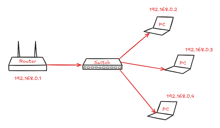
When you provide electricity to Router, mainboard will start a application at default IP, eg: 192.168.0.1 When you connect your PC to that Router via cable, Router will grant local IP to your PC.
In this case, Router is
DHCP
Server ~
Dynamic Host Configuration Protocol
To setup Router’s configuration, you can access default IP of Router: 192.168.0.1 in Browser.
Phase 2. When your Router connects to the internet
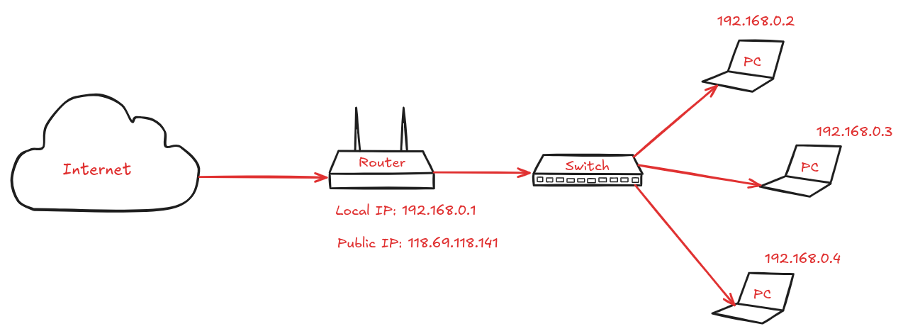
When your Router connects to the internet ( another router from
ISP
~
Internet Service Provider
), Router will get public IP, eg: 118.69.118.141
How network communication works ?
To understand communication process from sender to receiver, we use
OSI
model ~
Open Systems Interconnection
.
It's a
conceptual framework
or
reference model
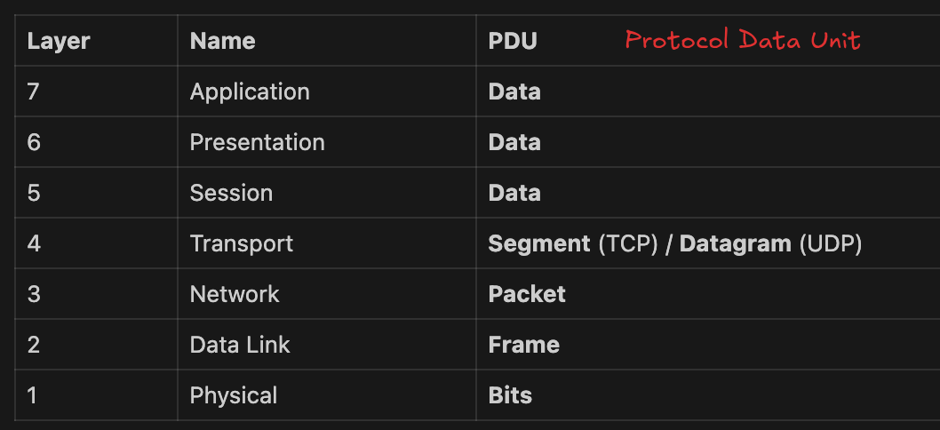
OSI model has 7 layers.
Layer 7: Application
Layer 6: Presentation
Layer 5: Session
Layer 4: Transport
Layer 3: Networking
Layer 2: Data link
Layer 1: Physical
⇒ Each computer will apply 7 layers of OSI model
The other devices like Switch, Router have its own layers in OSI model.
Router: Layer 3 - 2 - 1
Switch: Layer 2 - 1
Scenario: when you use Browser to view website
http://udemynote.com/. It means your computer communicate to my blog ‘s server or computer which host udemynote.com website.
Layer 7: Application
Responsibility
: work with user to prepare data to ready for network
Each software applications require network will be treated as application in layer 7
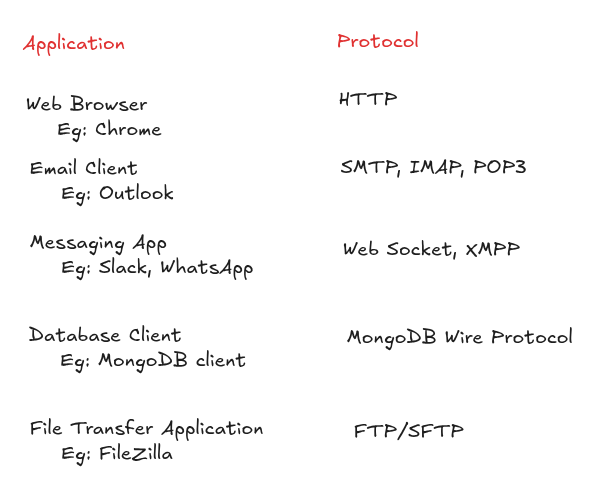
Application layer is as interface to the network.
In here,
From your computer, Browser is layer 7. Layer 7 is visualized via browser to:
render web page
init request by HTTP protocol
use DNS
There are some common Web server applications: Node.js, Apache, Nginx, etc. But my website (udemynote) uses Vercel Edge Network ~ acts like CDN + Nginx.
Layer 6: Presentation
Responsibility
: format data
Key functions:
Encode/Decode: Character encoding conversion (ASCII, EBCDIC, Unicode, UTF-8, etc.)
Encryption/Decryption - securing data for transmission: SSL, TLS
Compression/Decompression - reducing data size which takes less bandwidth to deliver easily Example:
gzip
(GNU zip) is a
data compression algorithm
that reduces file/data size before sending it over the network. Without gzip → send
80KB
With gzip → send
~12KB
(up to
70% smaller
)
Layer 5: Session
Responsibility
: keeping connection is alive.
Key functions:
Establish, manage, and terminate communication sessions between applications
Layer 4: Transport
Responsibility
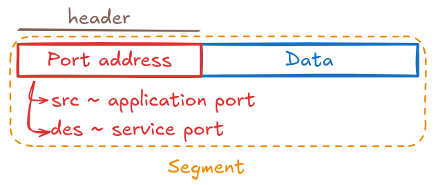
: delivery segments to right application/ service.
FYI, Client use applications ~ Server use services.
Client make request ~ Server fulfill the request.
Services are applications which are designed to run in the background.
Key functions:
Segmentation & Reassembly
Separate connection
Example:
src port: 49152 ← Chrome
des port: 443 ← Nginx Sometimes we see Nginx configuration like
server {
        listen               443 ssl;
}
What is segment ?
Segment is unit of data in Layer 4
Layer 4 takes data and break into Segment ( smaller pieces ) to delivery easily in the network.
So how to glue they back together to able to display at the Application layer ?
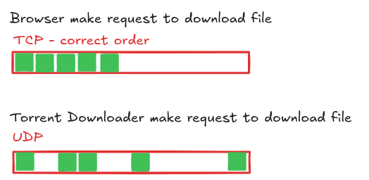
We need to control data flow via
ordered
protocol - TCP
From that, it guarantees the Application layer always gets data in the
correct order and complete
.
I will share detail in TCP in other article.
There are
2 main protocols
in Layer 4 — and a few others less commonly used:
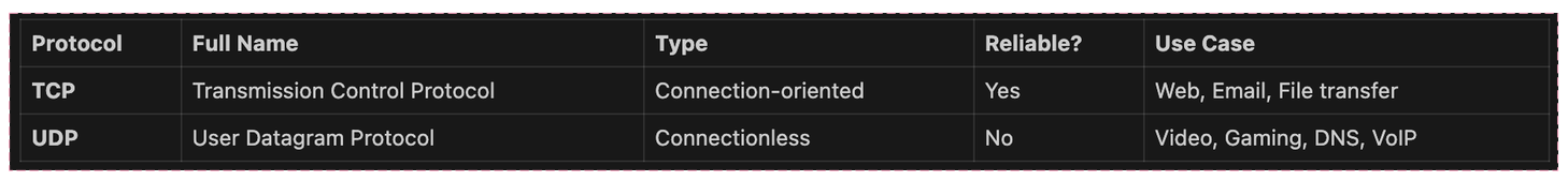
Unreliable delivery like teacher talk (delivery data) & don’t care student understand or not.
Size of Datagram in UDP > size of Segment in TCP ⇒ allow to send more data ⇒ UDP is faster
Layer 3: Network
Responsibility
: route packet from source to destination
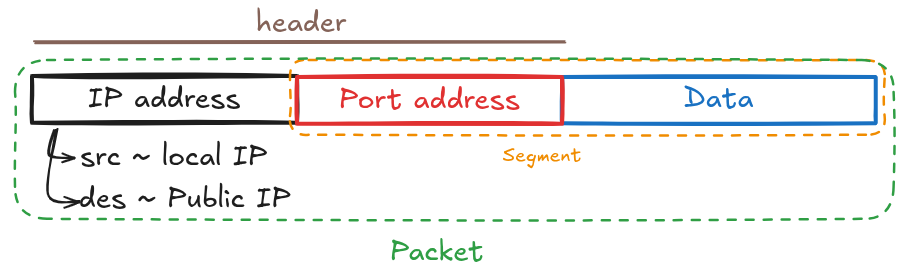
IP address identifies end device on a network.
Layer 2: Data link
Responsibility
: transfer frame between two directly connected devices on the same network
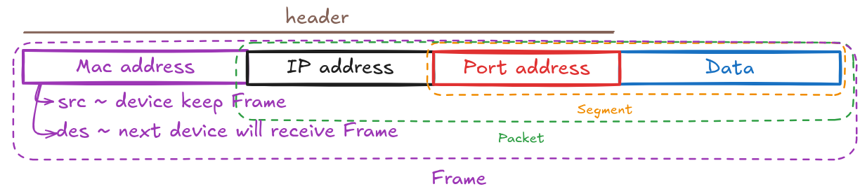
Mac address is
unique
and
can’t change
[?] How to get mac address of next device ? - ARP Resolution
If PC want to send data to the internet, next device will be Router which connects to the internet.
Based on IP of next device, we can detect its own Mac Address.
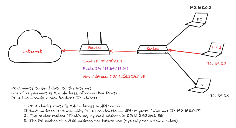
To view ARP cache
// Command: arp -a
? (192.168.0.1) at 00:1a:2b:3c:4d:5e on en0 permanent [ethernet]
To send data into LAN (Local Area Network), === IMAGE ===
When PC_A want to access service from PC_B, it requires to know local IP of PC_B first.
Then PC_A will send ARP request to get Mac Address of PC_B and update Mac Address of PC_B to be destination Mac Address in the package. From that, when send request to Switch, Switch will forward that to PC_B
Layer 1: Physical
Responsibility:
convert bits into electrical, light, or radio signals